
Rear Disc Brake Conversion Kit Installation: Complete Technical Protocol
Technical Overview: Disc Brake Conversion Fundamentals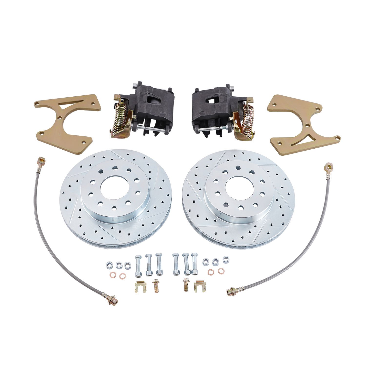
Rear disc brake conversion represents one of the most significant safety upgrades available for older vehicles originally equipped with drum brake systems. This conversion addresses fundamental limitations of drum brake technology, including heat dissipation capacity, wet weather performance, and maintenance accessibility.
Modern rear disc brake conversion kits provide standardized components engineered for specific vehicle applications. Proper installation requires understanding of brake system architecture, mechanical specifications, and integration requirements. This technical analysis provides comprehensive guidance for conversion installation.
System Architecture: Component Analysis
Core Conversion Kit Components
Standard rear disc brake conversion kits include essential components:
| Component | Function | Critical Specification |
|---|---|---|
| Brake caliper | Hydraulic pressure application to pads | Bore size must match master cylinder output |
| Rotor | Friction surface for stopping | Diameter and thickness per application |
| Mounting bracket | Caliper attachment to axle housing | Must match axle flange pattern |
| Parking brake mechanism | Integrated or auxiliary cable system | Functional requirement for street use |
| Brake lines | Hydraulic fluid delivery | Compatible fitting sizes and materials |
| Hardware | Mounting bolts, slide pins, clips | OEM-grade specifications |
Secondary Components Required
Additional components not always included in basic kits:
- Proportioning valve (adjusts front/rear brake bias)
- Brake flex lines (hose from hard line to caliper)
- Parking brake cables (if auxiliary system required)
- Wheel studs (if rotor requires different stud pattern)
- Caliper bracket bolts (high-tensile strength requirements)
Pre-Installation Assessment
Vehicle Compatibility Verification
Before beginning installation, verify vehicle-specific compatibility:
Axle identification. Confirm axle housing flange pattern matches conversion kit mounting configuration. Common patterns include:
- Ford 9″ (large flange bolts)
- GM 7.5″ / 8.5″ / 12-bolt
- Chrysler 8.25″ / 9.25″
- Ford 8.8″ (late model)
- Universal custom applications
Wheel stud pattern. Verify wheel stud circle diameter (PCD) matches intended wheels. Different rotor configurations may require different stud patterns.
Master cylinder compatibility. Rear disc brake systems operate at different pressure characteristics than drum systems. Master cylinder must provide appropriate rear circuit output or include integral proportioning.
Component Inspection Protocol
Inspect all components before installation:
- Verify caliper bore size matches system requirements
- Confirm rotor dimensions match specifications
- Check bracket mounting hole alignment
- Inspect all hardware for defects
- Verify parking brake mechanism completeness
- Confirm brake line fitting sizes and thread types
Installation Protocol: Mechanical Assembly
Rear Axle Preparation
Drum Brake Component Removal
Complete drum brake removal is prerequisite to conversion installation:
- Safely raise vehicle and support on jack stands
- Remove wheel assembly
- Release parking brake and disconnect parking brake cables
- Remove drum brake assembly per manufacturer procedure
- Inspect axle flanges for damage, corrosion, or irregularities
- Clean mounting surface thoroughly—remove all old gasket material, rust, and debris
- Check axle bearings for condition—replace if showing wear indicators
Axle Flange Inspection
The axle flange mounting surface must meet specific conditions:
- Flatness tolerance: 0.005″ maximum deviation
- Surface finish: Clean, bare metal without paint or coating
- Bolt hole condition: All threads intact, no cross-threading
- Center bore condition: Clean, no burrs or damage
Brake Rotor Installation
Rotor installation establishes the foundation for caliper positioning:
- Clean new rotor mating surfaces with brake cleaner
- Inspect rotor for shipping damage or defects
- Position rotor on axle flange—verify correct side (most rotors are directional)
- Install rotor retaining screws if provided—torque to 5-10 ft-lb
- Verify rotor spins freely without interference
- Check rotor runout with dial indicator—maximum 0.003″
Caliper Mounting Bracket Installation
Bracket installation positions the caliper relative to the rotor:
- Apply anti-seize compound to bracket mounting surfaces (where specified)
- Position bracket on axle flange
- Install mounting bolts—use new hardware as supplied
- Torque bolts in alternating pattern per specification
- Typical torque: 70-90 ft-lb for 1/2″ Grade 8 bolts
- Verify torque twice—once initially, once after brief operation
Caliper Installation
Caliper installation completes the primary mechanical assembly:
- Install brake pads per manufacturer instructions
- Verify pad slides freely in bracket mounting points
- Apply appropriate lubricant to slide pins (if applicable)
- Position caliper over rotor—verify correct orientation
- Thread slide bolts or mount bolts as specified
- Torque mounting hardware per specification:Slide bolts: 20-30 ft-lb
- Mounting bolts: Per bracket specification
Parking Brake Mechanism Integration
Parking brake integration varies by kit design:
Integrated Caliper Parking Brake
Some kits integrate parking brake function within the rear caliper:
- Install parking brake cable to mechanism per kit instructions
- Verify cable routing—avoid sharp bends or binding
- Apply lubricant to cable housing (where accessible)
- Adjust parking brake mechanism per specification
- Verify parking brake applies and releases completely
Auxiliary Parking Brake System
Where integrated parking brake is not provided:
- Install auxiliary parking brake mechanism per kit instructions
- Route cables avoiding heat sources and moving components
- Connect to existing parking brake system if applicable
- Verify equal tension on both cables
- Adjust for proper application (typically 3-5 clicks)
Hydraulic System Integration
Brake Line Routing
Proper brake line routing prevents system failures:
| Requirement | Specification |
|---|---|
| Minimum clearance from heat sources | 3″ from exhaust components |
| Support spacing | Every 18-24 inches |
| Bend radius minimum | 6x line diameter |
| Protection from road hazards | Required below vehicle |
- Route new brake lines using compatible tubing (copper-nickel or stainless steel recommended)
- Use bubble flares or appropriate fittings for connection points
- Install brake line supports at specified intervals
- Route away from moving suspension components
- Verify no chafing potential during suspension travel
Master Cylinder Integration
Master cylinder selection affects system performance:
Proportioning valve requirement. Rear disc brakes require reduced pressure compared to front discs. Proportioning valve integration is mandatory:
- Inline proportioning valves mount between master cylinder and rear circuits
- Some master cylinders include integral proportioning
- Adjustment range typically 30-50% pressure reduction
Residual pressure valve. If the system does not include integral residual check valve, installing a 10 PSI residual valve in the rear circuit prevents air ingestion during parking:
- 10 PSI valves are standard for disc brake systems
- Installs in hard line between master cylinder and rear circuit
- Prevents pad wear from gradual fluid seepage
System Bleeding Protocol
Complete air removal from brake system is mandatory before vehicle operation:
- Fill master cylinder with DOT 3 or DOT 4 brake fluid (per manufacturer specification)
- Begin bleeding at wheel furthest from master cylinder
- Use pressure bleeder or manual bleeding method
- Continue bleeding until bubble-free fluid emerges
- Repeat for each wheel in sequence
- Check master cylinder level throughout bleeding process
- Verify firm pedal feel before test driving
Torque Specifications: Complete Reference
Critical Fastener Torque Values
| Application | Torque Specification | Notes |
|---|---|---|
| Axle flange to bracket | 70-90 ft-lb | Grade 8 hardware |
| Caliper mount bolts | 70-90 ft-lb | Per bracket specification |
| Slide pins | 20-30 ft-lb | Lubricate before installation |
| Brake line fittings | 10-15 ft-lb | Flare fitting torque |
| Rotor retaining screws | 5-10 ft-lb | If equipped |
| Wheel lugs | Per wheel specification | Typically 65-90 ft-lb |
Post-Installation Verification
Mechanical Inspection Protocol
Before vehicle operation, complete comprehensive verification:
- Verify all fasteners are properly torqued
- Confirm brake lines are properly routed and supported
- Check that wheels spin freely without rotor contact
- Verify parking brake mechanism functions properly
- Confirm brake pedal feel is firm (no sponginess)
- Check brake fluid level in master cylinder
- Verify no fluid leaks at any connection point
Initial Test Protocol
Controlled test procedure before public road use:
- In safe location, apply brakes from low speed (5-10 MPH)
- Verify braking action occurs at each wheel
- Listen for any unusual sounds—grinding, scraping, or squealing
- Check for pulling—vehicle should track straight
- Test parking brake application and release
- Verify brake pedal remains firm during repeated applications
- Complete full system burnish per pad manufacturer recommendations
System Integration: Related Components
Proportioning Valve Adjustment
Proper brake bias affects vehicle stability:
| Condition | Indication | Adjustment |
|---|---|---|
| Rear lockup before front | Rear brakes too aggressive | Increase proportioning |
| Front lockup only | Rear brakes insufficient | Decrease proportioning |
| Balanced stopping | Optimal condition | No adjustment required |
Brake Controller Integration
Vehicles with anti-lock braking systems (ABS) require specific consideration:
- ABS module must recognize rear disc brake circuit
- Some ABS systems require proportioning valve integration through module programming
- Professional diagnostic verification recommended for ABS-equipped vehicles
Common Installation Errors
Mechanical Assembly Errors
| Error | Consequence | Prevention |
|---|---|---|
| Insufficient bracket torque | Bracket loosening during operation | Verify torque twice, use thread locker |
| Incorrect pad orientation | Brake failure, excessive wear | Follow installation diagram carefully |
| Missing slide pin lubrication | Caliper sticking, uneven wear | Lubricate all contact surfaces |
| Rotor face contamination | Brake noise, reduced friction | Clean rotor with brake cleaner only |
Hydraulic System Errors
| Error | Consequence | Prevention |
|---|---|---|
| Improper flare technique | Leak at fitting | Practice on scrap tubing first |
| Cross-threaded fittings | Fitting damage, leaks | Thread by hand first |
| Insufficient bleeding | Spongy pedal, brake failure | Complete bleeding procedure fully |
| Wrong fluid type | Seal damage, system failure | Use manufacturer-specified fluid |
FAQ: Technical Clarifications
Q: Can I install a rear disc brake conversion kit without professional assistance?
A: Installation is achievable for experienced DIY mechanics with appropriate tools and mechanical competence. Required tools include torque wrenches (multiple sizes), flare tool, brake bleeding equipment, and general hand tools. Professional installation is recommended for vehicles with ABS systems due to diagnostic requirements.
Q: What causes the brake pedal to feel spongy after installation?
A: Spongy pedal feel indicates air remaining in the hydraulic system. Complete bleeding procedure must be repeated until pedal feel is firm. Check for hidden air in flexible brake lines—these require cycling multiple times during bleeding. Persistent sponginess may indicate seal damage from contamination or incorrect fluid type.
Q: Why is a proportioning valve necessary for rear disc brake conversion?
A: Disc brakes generate braking force differently than drum brakes. Without proportioning, rear disc brakes would engage more aggressively than front brakes, causing rear lockup and vehicle instability. Proportioning valves reduce rear circuit pressure to match vehicle weight distribution and brake balance requirements.
Q: Can I reuse existing brake lines from drum brake system?
A: Generally no—drum brake systems use different line configurations and may not provide adequate routing for disc brake calipers. New brake lines ensure proper routing, appropriate fittings, and correct length. Reused lines may contain hidden damage from disconnection.
Q: How do I determine correct parking brake adjustment?
A: Parking brake adjustment procedures vary by kit design. Generally, adjust until parking brake applies fully within 3-5 clicks of lever travel, with rear wheels locked when tested on incline. Excessive adjustment causes drag; insufficient adjustment results in inadequate parking hold.
Q: What maintenance intervals apply after disc brake conversion?
A: Rear disc brake maintenance intervals match front disc brake schedules. Inspect pads every 15,000-20,000 miles, replace pads when reaching 2-3mm thickness. Check slide pin lubrication annually. Replace brake fluid every 2-3 years per manufacturer recommendation.
Where to Buy a Where to Buy a Front Disc Brake Conversion Kit?
If you’re looking for a reliable supplier, it’s important to choose a manufacturer that offers:
- Stable product quality
- Consistent supply
- Wholesale support
- OEM branding options
For bulk orders or reseller inquiries, you can check this product page:
If you’re looking for a reliable supplier, it’s important to choose a manufacturer that offers:
- Stable product quality
- Consistent supply
- Wholesale support
- OEM branding options
For bulk orders or reseller inquiries, you can check this product page: