
How to install throwout bearing on clutch fork
The throwout bearing, also known as release bearing, serves as the critical interface between the clutch fork and the clutch pressure plate fingers. When the clutch pedal is depressed, the fork pivots on its ball stud, pushing the throwout bearing against the pressure plate diaphragm spring. This action releases the clutch disc, enabling gear changes.
The clutch fork connects to the throwout bearing through spring clips that secure the bearing in the fork’s recessed collar. Proper installation ensures the bearing can pivot freely while maintaining positive engagement with the fork during operation. Incorrect installation leads to bearing failure, clutch operation problems, and potentially complete drivetrain damage.
THROWOUT BEARING SYSTEM COMPONENTS
MECHANICAL RELEASE SYSTEM COMPONENTS
Clutch fork: Pivots on ball stud to actuate bearing. Must pivot freely, not bind.
Throwout bearing: Transfers force to pressure plate. Must slide on transmission input shaft.
Spring clips: Secures bearing in fork. Must fully engage bearing collar.
Ball stud: Fork pivot point. Grease pocket requires lubrication.
Input shaft bearing: Supports transmission input shaft. Critical alignment reference.
HYDRAULIC RELEASE SYSTEM COMPONENTS
Hydraulic actuator: Converts fluid pressure to movement. Must be purged of air.
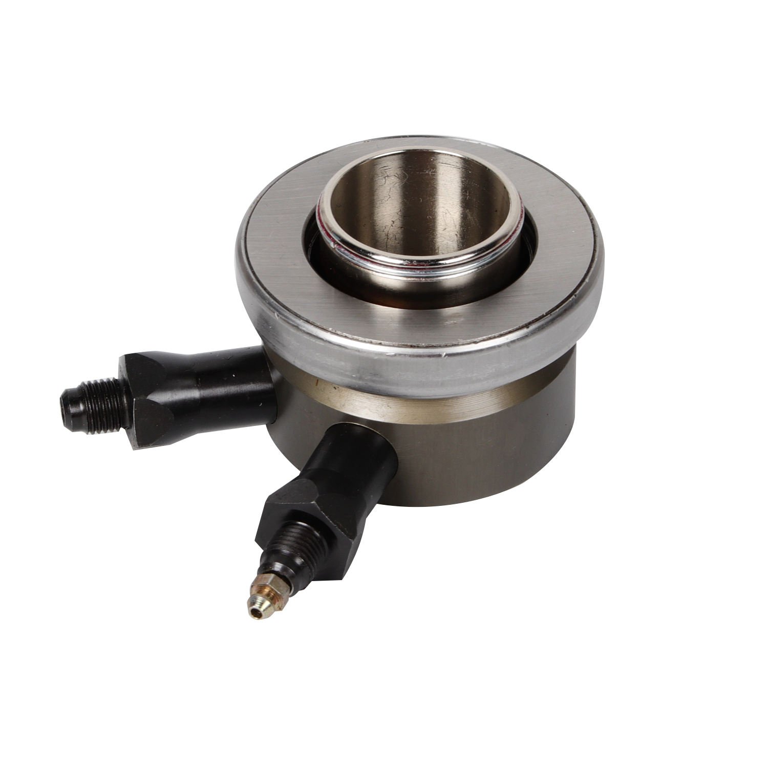
Release bearing: Integrated hydraulic design. May have different mounting.
Hydraulic line: Transfers pressure. Must be properly routed.
Slave cylinder: Provides actuation pressure. Bleeding required after install.
PRE-INSTALLATION PREPARATION
TOOLS AND MATERIALS REQUIRED
High-temperature wheel bearing grease: Lubrication. Do not use regular grease.
Snap ring pliers: Clip removal and installation. Appropriate size for clips.
Pry bar or screwdriver: Fork manipulation. Non-marring tip preferred.
Clean rags: Surface cleaning. Lint-free preferred.
Torque wrench: Fastener tightening. Proper range for application.
Alignment dowels: Transmission installation. Prevents misalignment.
BEARING AND FORK INSPECTION
Before installation, verify component condition:
1. Inspect throwout bearing: Check for smooth rotation, no roughness or noise. Verify collar clips are present and intact. Inspect bearing face for wear or scoring.
2. Inspect clutch fork: Verify pivot point moves freely without binding. Check spring clip engagement points for damage or wear. Inspect fork arms for cracks or distortion.
3. Inspect transmission input shaft: Clean and inspect seal area. Verify smooth surface for bearing to slide upon. Check for any damage that would impede bearing installation.
THROWOUT BEARING INSTALLATION: MECHANICAL RELEASE SYSTEM
STANDARD INSTALLATION PROCEDURE
Step 1: Fork preparation
1. Position clutch fork with concave side facing up.
2. Inspect fork collar where bearing will seat.
3. Verify spring clips are present in fork collar.
4. Clean any debris or old lubricant from fork cavity.
Step 2: Bearing preparation
1. Inspect throwout bearing for condition.
2. Verify bearing slides freely on transmission input shaft surface.
3. Apply thin layer of high-temperature wheel bearing grease to the transmission input shaft where bearing will slide, the fork pivot ball pocket, and the release bearing contact surface facing the pressure plate.
4. Do not over-grease—excess grease attracts contaminants.
Step 3: Bearing attachment to fork
1. Position throwout bearing with collar facing down toward fork.
2. Align bearing collar with fork recessed area.
3. Press bearing into fork until spring clips engage collar groove.
4. Verify both clips are fully seated in collar groove.
5. Pull gently on bearing to confirm secure attachment.
6. Bearing should not pull free from fork when clips are engaged.
Step 4: Fork installation on ball stud
1. Apply small amount of grease to ball stud pivot point.
2. Align fork ball pocket with ball stud.
3. Press fork onto ball stud.
4. Verify fork pivots freely without binding.
5. If fork binds, remove and check for interference or debris.
Step 5: Transmission installation coordination
1. With fork installed on ball stud, position transmission for installation.
2. Guide throwout bearing onto transmission input shaft.
3. Ensure bearing slides over input shaft as transmission moves into position.
4. Watch that fork does not bind or pull away from bearing during transmission installation.
CRITICAL INSTALLATION POINTS
Clip engagement: Both clips must fully seat in groove. Pull-test to verify.
Grease application: Thin layer, not excess. Prevents contamination.
Fork pivoting: Must move freely after installation. Check before final assembly.
Bearing alignment: Must slide on shaft without binding. Verify smooth movement.
THROWOUT BEARING INSTALLATION: HYDRAULIC RELEASE SYSTEM
HYDRAULIC BEARING PREPARATION
Hydraulic release bearings integrate the bearing with a hydraulic cylinder, requiring different installation procedures than mechanical systems.
Step 1: Hydraulic system preparation
1. Install provided mounting studs in transmission case (2 o’clock position typically).
2. Verify hydraulic line routing before bearing installation.
3. Inspect hydraulic fitting for damage.
4. Ensure system is purged of air before operation.
Step 2: Bearing attachment
1. Position bearing with hydraulic cylinder facing correct direction.
2. Align mounting studs with bearing flange holes.
3. Secure bearing with provided hardware.
4. Torque mounting fasteners to specification.
5. Connect hydraulic line with proper fitting.
Step 3: System verification
1. Bleed hydraulic system after installation.
2. Verify no leaks at fittings.
3. Test clutch pedal operation.
4. Confirm smooth release and engagement.
TRANSMISSION INSTALLATION COORDINATION
PROPER SEQUENCE FOR INSTALLATION
The throwout bearing and clutch fork installation must coordinate with transmission installation. Proper sequence prevents component damage and ensures correct operation.
Pre-installation phase: Install fork on ball stud. Verify it pivots freely without binding.
Pre-installation phase: Attach bearing to fork. Verify clips fully engaged.
Transmission entry phase: Guide bearing onto input shaft. Verify it slides without resistance.
Transmission seating phase: Monitor fork position. Verify it does not bind or pull away.
Final phase: Verify complete engagement. All connections secure.
COMMON INSTALLATION ERRORS
Fork clips not fully seated: Causes bearing to fall off during operation. Prevention: Pull-test before continuing.
Excessive grease: Causes contamination of clutch disc. Prevention: Use minimal, appropriate amount.
Fork binds on ball stud: Causes erratic clutch operation. Prevention: Verify free movement.
Bearing not aligned on shaft: Causes difficult transmission install. Prevention: Guide carefully during entry.
Fork pulls away from bearing: Causes loss of clutch actuation. Prevention: Monitor during transmission install.
LUBRICATION REQUIREMENTS
APPROPRIATE LUBRICANT SELECTION
High-temperature wheel bearing grease: For input shaft and bearing surface. Do not use regular chassis grease.
Multi-purpose grease: For fork pivot ball (minimal amount only). Do not use excessive amounts.
Clutch fork lubricant: For specified contact points only. Do not use unspecified products.
LUBRICATION POINTS
Apply lubricant to these four areas:
1. Input shaft bearing surface: Apply thin film where bearing slides.
2. Fork pivot ball: Apply light coating in pocket.
3. Bearing contact face: Apply thin layer on pressure plate contact surface.
4. Release bearing collar: Apply minimal amount if specified by manufacturer.
POST-INSTALLATION VERIFICATION
PHYSICAL INSPECTION
Bearing attachment: Pull on bearing to verify it does not pull free from fork.
Fork movement: Rotate fork by hand to verify it pivots freely without binding.
Bearing alignment: Perform visual inspection to verify it is centered on input shaft.
Clearance check: Verify adequate clearance with no contact to surrounding components.
FUNCTIONAL VERIFICATION
1. Pedal operation: With transmission installed, operate clutch pedal.
2. Engagement feel: Pedal should feel firm with defined engagement point.
3. Release action: Bearing should push forward smoothly when pedal is depressed.
4. Return action: Fork should return fully when pedal is released.
TROUBLESHOOTING INSTALLATION ISSUES
BEARING FALLS OFF FORK
Spring clips not fully engaged: Solution: Remove and reinstall clips properly.
Worn clips: Solution: Replace clips or bearing assembly.
Incorrect bearing: Solution: Verify application match.
FORK BINDING AFTER INSTALLATION
Debris on ball stud: Solution: Clean and relubricate.
Misaligned ball stud: Solution: Check stud orientation.
Bent fork: Solution: Replace fork.
Improper seating: Solution: Remove and reinstall correctly.
TRANSMISSION INSTALLATION RESISTANCE
Bearing not aligned with shaft: Solution: Reposition transmission.
Fork binding: Solution: Check fork installation.
Input shaft damaged: Solution: Inspect and repair shaft.
MAINTENANCE CONSIDERATIONS
INSPECTION SCHEDULE
Every oil change: Check for fluid leaks at hydraulic bearing.
Every clutch service: Inspect bearing condition and fork movement.
Annually: Verify fork pivots freely and lubricate if needed.
WEAR INDICATORS
Watch for symptoms indicating bearing or fork problems:
Squealing or grinding when clutch is engaged.
Difficulty shifting gears.
Spongy or inconsistent clutch pedal.
Noise from transmission bellhousing area.
Clutch not fully disengaging.
FAQ: TECHNICAL CLARIFICATIONS
Q: How do you install a throwout bearing on a clutch fork?
A: Installation involves securing the throwout bearing to the fork using spring clips that engage the bearing collar. Position the bearing collar into the fork’s recessed area and press until both clips fully seat in the collar groove. Pull-test to verify secure attachment. Apply appropriate lubricant to bearing contact surfaces and fork pivot point before installing fork on ball stud and coordinating with transmission installation.
Q: How do you know if the throwout bearing is properly installed?
A: Proper installation is verified by pulling on the bearing—if it does not pull free from the fork, clips are engaged. The fork should pivot freely on the ball stud without binding. During transmission installation, the bearing should slide onto the input shaft smoothly without resistance. After installation, the clutch pedal feels firm with smooth engagement and release action.
Q: What happens if throwout bearing clips are not fully seated?
A: Unseated clips allow the bearing to fall off the fork during operation. This creates complete clutch failure—the pedal may feel normal, but the clutch will not disengage, preventing gear changes. The vehicle becomes inoperable until the bearing is properly installed. Always pull-test the bearing after installation to verify clip engagement.
Q: Should you grease the throwout bearing before installation?
A: Yes, appropriate lubrication is essential for proper operation. Apply high-temperature wheel bearing grease to the transmission input shaft surface where the bearing slides, the bearing face that contacts the pressure plate, and the fork pivot ball pocket. Use minimal amounts—excessive grease attracts contaminants and can damage the clutch disc.
Q: Can you install throwout bearing with transmission already in vehicle?
A: Yes, in some applications the bearing can be installed from below after removing the transmission. However, this is more difficult than pre-installation. For easier installation, attach the bearing to the fork before installing the transmission, then guide the bearing onto the input shaft as the transmission slides into position. Some vehicles may require transmission removal for bearing access.
Q: What type of grease should be used for throwout bearing installation?
A: Use high-temperature wheel bearing grease designed for bearing applications. Do not use regular chassis grease or multipurpose grease, as these may not withstand the temperatures generated at the bearing contact point. Some manufacturers specify particular products—always verify application requirements. Apply sparingly to prevent contamination of the clutch disc friction material.