Universal Joint Installation: Complete Technical Protocol
Technical Overview: Universal Joint System Architecture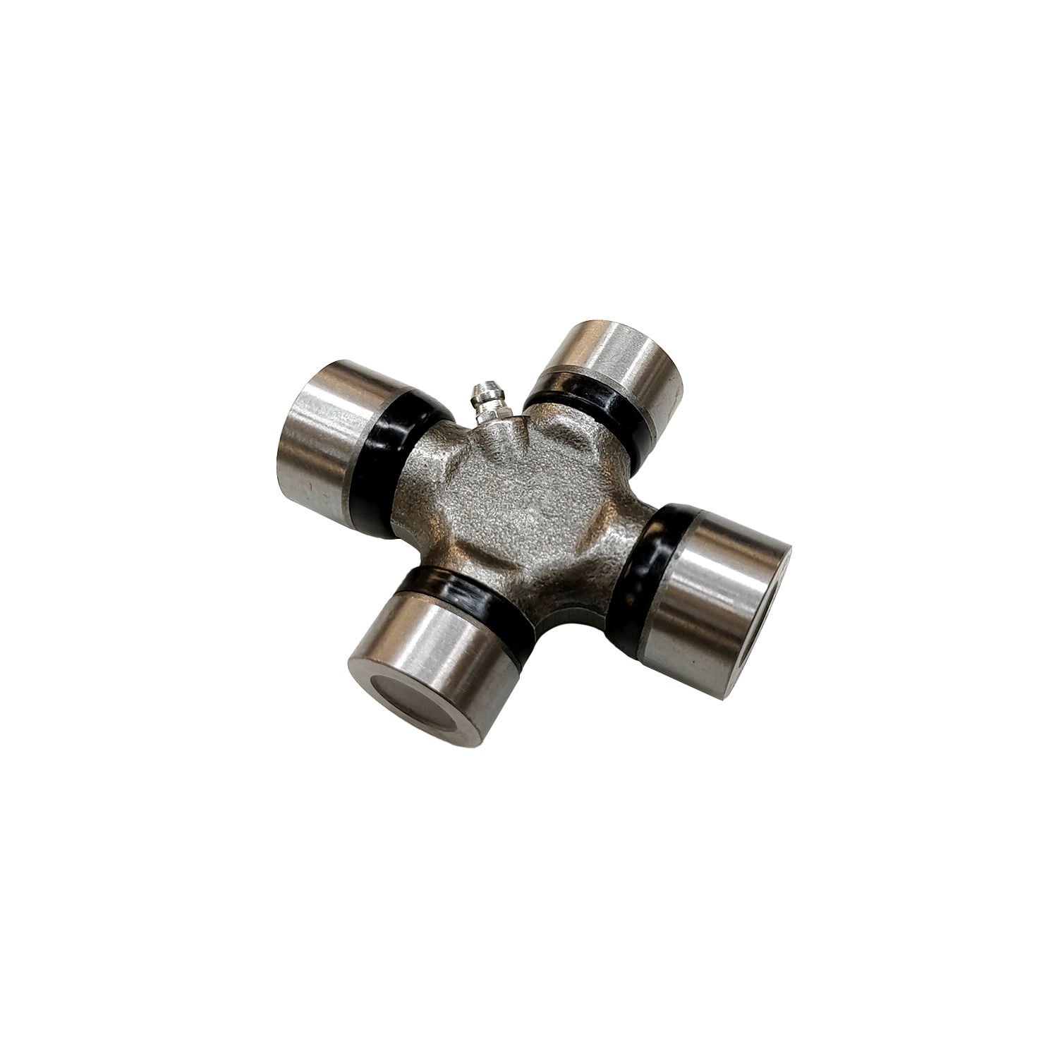
Universal joints represent the fundamental mechanical linkage connecting rotating drivetrain components at angular positions. Proper installation directly impacts drivetrain longevity, vibration characteristics, and operational reliability. This technical analysis provides comprehensive methodology for universal joint installation across automotive applications.
Universal Joint Fundamentals: Design Analysis
Cross and Bearing Assembly
The universal joint cross assembly comprises four needle bearing assemblies positioned at each cross arm, with bearing cups pressed into yoke receiving bores:
| Component | Function | Critical Specification |
|---|---|---|
| Cross | Central torque transfer member | Heat-treated steel |
| Needle bearings | Rotational interface | Lubricated interface |
| Bearing cups | Needle containment | Press-fit in yoke bores |
| Snap rings | Retention mechanism | Spiral or clip-style |
Yoke Configuration
Universal joint yokes are manufactured in two primary configurations:
Single-cardan yokes accept cross bearing cups on a single plane. This configuration permits angular deflection in one direction while maintaining fixed alignment in the perpendicular plane.
Double-cardan yokes incorporate two cross assemblies at each joint location, creating a constant-velocity joint that eliminates operating angle-induced vibration. This configuration is standard for modern automotive driveshaft applications.
Pre-Installation Assessment
Component Verification
Before installation, verify universal joint compatibility:
Bearing cup dimensions. Cross bearing cup diameters must match yoke bore specifications. Standard sizes include:
- 0.625″ (small U-joints)
- 0.750″ (medium U-joints)
- 0.875″ (large U-joints)
- 1.062″ (heavy-duty applications)
Splined bore configuration. Driveshaft-side U-joints typically feature female splined bores matching driveshaft specifications. Verify spline count and pitch match application requirements.
Operating angle compatibility. U-joint operating angles must not exceed manufacturer specifications. Typical maximum angles:
- Standard automotive: 20-25 degrees total
- Heavy-duty applications: 15-20 degrees total
- Constant-velocity joints: 35-45 degrees total
Tool Requirements
Proper installation requires specific tooling:
| Tool | Specification | Application |
|---|---|---|
| U-joint press | Capacity for bearing cup removal/installation | Primary assembly tool |
| Snap ring pliers | Internal and external styles | Retention ring installation |
| Calipers | 0.001″ resolution | Bearing cup measurement |
| Torque wrench | Appropriate range | Flange yoke bolt specification |
| Press plates | Matching bearing cup diameter | Installation support |
Installation Protocol: Cross and Bearing Assembly
Yoke Preparation
Proper yoke preparation ensures reliable joint assembly:
- Inspect yoke bores for corrosion, burrs, or surface irregularities
- Clean bore surfaces with brake cleaner or appropriate solvent
- Verify bearing cup fit clearance (0.001″-0.003″ press fit)
- Check snap ring grooves for damage or deformation
- Verify snap ring seats fully in groove without interference
Cross Installation Sequence
Phase One: Initial Bearing Cup Installation
- Position one yoke in press fixture
- Apply lubricant to bearing cup outer surface (assembly lube recommended)
- Align bearing cup with yoke bore
- Apply press force until bearing cup seats in bore
- Verify bearing cup seats fully against bore shoulder
- Install snap ring in bearing cup groove
- Verify snap ring is fully seated in groove
Phase Two: Cross Assembly
- Pack needle bearings with appropriate lubricant (EP grease or moly disulfide)
- Install needle bearings in two opposing cross arms
- Position cross assembly in yoke with bearing cups installed
- Verify cross rotates freely in bearing cups
- Install remaining needle bearings in opposing cross arms
Phase Three: Final Bearing Cup Installation
- Align remaining bearing cups with yoke bores
- Apply assembly lubricant to bearing cup surfaces
- Apply press force until bearing cup seats in bore
- Verify cross rotates freely through full 360-degree rotation
- Install snap rings in remaining bearing cup grooves
- Verify all snap rings are fully seated in grooves
Installation Verification Protocol
Post-installation verification confirms proper assembly:
- Rotate cross through full 360-degree rotation
- Verify smooth rotation without binding or roughness
- Check for radial play (maximum 0.001″)
- Check for axial play (maximum 0.005″)
- Verify snap ring retention in all four positions
- Confirm cross is centered in yoke bores
Driveshaft Installation Protocol
Slip Yoke Assembly
When driveshaft incorporates slip yoke assembly:
- Apply lubricant to splined shaft
- Install slip yoke on splined shaft
- Verify slip yoke engages fully on shaft
- Check slip yoke movement through full travel
- Verify centering and alignment
Flange Yoke Connection
Direct flange connection requires specific procedure:
- Clean mating surfaces (flange and differential pinion flange)
- Inspect flange bolt holes for damage
- Position driveshaft flange against pinion flange
- Align bolt holes
- Install flange bolts with appropriate thread locker
- Torque flange bolts in alternating pattern
- Verify torque per specification (typically 65-90 ft-lb)
Operating Angle Verification
Proper driveshaft installation requires angle verification:
| Measurement Location | Specification |
|---|---|
| Transmission output angle | Measure with bubble protractor |
| Pinion angle | Measure with bubble protractor |
| Driveshaft angle | Measure with bubble protractor |
| Operating angle | Difference between transmission and pinion angles |
| Angularity index | Balance compensation factor |
Operating angles exceeding specifications cause vibration and accelerated joint wear. Professional alignment verification is recommended.
Torque Specifications: Complete Reference
Flange Yoke Fastener Torque
| Application | Torque Specification | Hardware Grade |
|---|---|---|
| Standard automotive | 65-90 ft-lb | Grade 8 |
| Light truck | 80-100 ft-lb | Grade 8 |
| Heavy-duty truck | 100-130 ft-lb | Grade 8 |
| Spiral flange bolts | 35-45 ft-lb | Grade 5 |
Slip Yoke Retention
| Retention Method | Specification |
|---|---|
| Bolt-on retainer | 25-35 ft-lb |
| C-clip retention | No torque—mechanical fit |
| Pinion flange nut | Per manufacturer specification |
Quality Verification: Post-Installation Protocol
Visual Inspection
Post-installation inspection confirms proper assembly:
- Verify all snap rings are fully seated
- Check bearing cup alignment in yoke bores
- Inspect for any signs of interference or binding
- Verify driveshaft alignment and angle
- Check for any clearance issues during rotation
Functional Testing
Operational verification confirms joint function:
- Rotate driveshaft through full rotation
- Verify smooth operation without binding
- Check for vibration at operating RPM
- Verify drivetrain alignment during acceleration
- Monitor for unusual noise or movement
Common Installation Errors
Assembly Errors
| Error | Consequence | Prevention |
|---|---|---|
| Insufficient lubrication | Accelerated wear, noise | Pack bearings fully with appropriate lubricant |
| Bearing cup misalignment | Cross binds during installation | Use press alignment fixtures |
| Snap ring improperly seated | Joint failure during operation | Verify all snap rings fully seated |
| Cross installed backwards | Increased wear, limited travel | Install cross with lube fittings accessible |
Driveshaft Installation Errors
| Error | Consequence | Prevention |
|---|---|---|
| Incorrect operating angle | Vibration, joint failure | Measure and verify angles |
| Imbalanced driveshaft | High-speed vibration | Professional balancing required |
| Missing centering marks | Drivetrain misalignment | Align factory marks during assembly |
| Incorrect flange bolt torque | Flange separation | Torque to specification |
Maintenance Protocol: Service Intervals
Inspection Schedule
Regular inspection identifies developing issues:
| Service Interval | Inspection Items |
|---|---|
| Every30,000 miles | Visual inspection, play check |
| Every 60,000 miles | Lubrication (if serviceable) |
| At fluid service | Driveshaft inspection |
Lubrication Requirements
Greasable U-joints require periodic lubrication:
- Use appropriate grease (EP lithium or moly-disulfide)
- Pump grease until fresh grease emerges from seals
- Avoid over-greasing (seals may rupture)
- Wipe excess grease from exterior
Non-greasable (sealed) U-joints require replacement when service indicators appear—typically vibration, play, or noise.
FAQ: Technical Clarifications
Q: What causes universal joint failure?
A: Primary failure mechanisms include inadequate lubrication, excessive operating angles, contamination from water or debris, fatigue from cyclic loading, and corrosion of bearing surfaces. Regular inspection and maintenance addresses these factors. Operating angles exceeding specifications accelerate failure significantly.
Q: Can I reuse existing universal joints during driveshaft removal?
A: Universal joints removed for inspection or access may be reused if bearing cups show no signs of galling, needle bearings roll freely without roughness, and snap ring retention is secure. Any signs of roughness, play, or contamination indicate replacement is necessary.
Q: What torque specification applies to flange yoke bolts?
A: Torque specifications vary by application and hardware grade. Standard automotive applications typically require 65-90 ft-lb with Grade 8 hardware. Heavy-duty applications may require 100-130 ft-lb. Always verify manufacturer specifications for specific applications.
Q: How do I verify proper universal joint installation?
A: Post-installation verification includes smooth rotation through 360 degrees without binding, radial play under 0.001″, axial play under 0.005″, and fully seated snap rings in all four positions. Driveshaft should spin freely without vibration at operating RPM.
Q: Can I install universal joints without a press?
A: Professional installation requires a press for proper bearing cup installation and removal. While hammer and socket methods exist, these techniques risk component damage and improper assembly. Press installation ensures proper seating and alignment. Professional shops possess appropriate equipment.
Q: What indicates universal joint replacement is necessary?
A: Replacement indicators include visible play when grasping driveshaft and attempting rotation, roughness or binding during rotation, clicking or clunking during load changes, and vibration during acceleration. Any of these symptoms warrant inspection and likely replacement.
Where to Buy a Where to Buy a Drive Shaft Combination Conversion U Joint?
If you’re looking for a reliable supplier, it’s important to choose a manufacturer that offers:
- Stable product quality
- Consistent supply
- Wholesale support
- OEM branding options
For bulk orders or reseller inquiries, you can check this product page:
If you’re looking for a reliable supplier, it’s important to choose a manufacturer that offers:
- Stable product quality
- Consistent supply
- Wholesale support
- OEM branding options
For bulk orders or reseller inquiries, you can check this product page: