How to Install Upper Tubular Control Arms: Complete Suspension Upgrade Guide
Control arms are the load-bearing connections between your vehicle’s chassis and its wheels. They control wheel position, manage suspension geometry, and absorb the forces that travel through the chassis during acceleration, braking, and cornering. When you upgrade to upper tubular control arms, you’re replacing the factory stamped-steel or composite arms with precision-engineered tubular steel or aluminum components that offer improved strength, adjustability, and performance characteristics.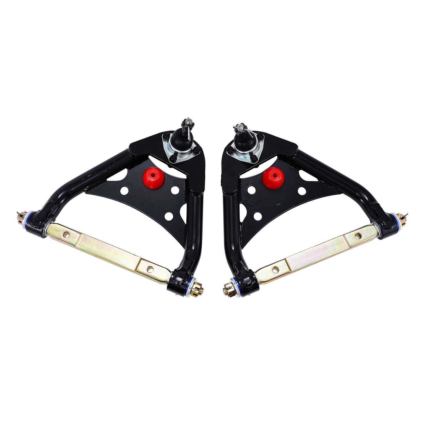
Installing upper tubular control arms is one of the most impactful suspension upgrades you can make. Whether you’re building a track-focused performance machine, a street-driven show car, or simply replacing worn-out factory components, tubular control arms deliver measurable improvements in handling response, camber control, and overall suspension geometry. This guide walks you through the complete installation process, from preparation through final alignment.
Understanding Upper Control Arms
Before beginning the installation, understanding what upper control arms do and why tubular designs offer advantages helps you appreciate the upgrade and install it correctly.
The Role of Upper Control Arms
Your vehicle’s upper control arms connect the top of the wheel assembly to the chassis. They serve several critical functions:
Wheel Positioning: The upper control arm, working with the lower control arm, positions the wheel hub vertically and controls its lateral and longitudinal position. This positioning determines camber angle, caster angle, and their changes during suspension travel.
Load Management: During cornering, braking, and acceleration, forces transfer through the control arms to the chassis. The control arms must handle these loads without excessive deflection or failure.
Suspension Geometry Control: As the suspension compresses and extends, the control arms guide the wheel through its arc of movement. Upper control arm positioning affects how camber changes during suspension travel—critical for maintaining tire contact with the road.
Bushing Isolation: Factory control arms typically use rubber bushings that isolate road vibrations from the chassis while allowing the necessary rotational movement. Aftermarket tubular arms often use polyurethane or spherical bearings for different performance characteristics.
Why Upgrade to Tubular Control Arms
Factory stamped-steel control arms serve their intended purpose admirably—they provide adequate strength for normal driving while offering acceptable isolation from road harshness. However, they have limitations that become apparent during performance driving:
Improved Strength: Tubular steel control arms are significantly stronger than stamped steel. They resist bending and twisting loads better, maintaining precise suspension geometry even under extreme conditions. This strength becomes valuable during hard cornering, aggressive launches, and repeated track use.
Reduced Deflection: Factory arms can flex slightly under load, creating a disconnected feeling during aggressive driving. Tubular arms’ stiffer construction provides more immediate response to driver inputs, making the car feel more directly connected to the road.
Camber Control: Many tubular upper control arms offer camber adjustment. Factory arms fix camber at a single position; adjustable tubular arms let you fine-tune camber for your specific tires, driving style, and alignment requirements.
Weight Reduction: Steel tube with strategic material removal often weighs less than the factory stamped-steel arm it replaces. Reducing unsprung weight improves suspension response and reduces the loads on other suspension components.
Durability for Performance Use: Factory bushings degrade over time, especially in performance driving applications. Aftermarket tubular arms often use more durable bearing materials that maintain their characteristics over extended service life.
Types of Upper Tubular Control Arms
Upper tubular control arms come in various designs, each with different characteristics:
Fixed Camber Arms: These non-adjustable arms set camber at a predetermined position. They’re simpler, less expensive, and appropriate when you know exactly what camber setting you need.
Adjustable Camber Arms: Incorporating adjustable pillow balls or eccentric bushings, these arms let you fine-tune camber for optimal tire contact during your specific driving conditions. Track-focused builds typically use adjustable arms.
Caster-Split Arms: Some designs allow caster adjustment by changing the relationship between upper and lower control arm mounting points. This affects steering feel and straight-line stability.
Steel vs. Aluminum: Tubular control arms are typically steel or aluminum. Steel arms are generally less expensive and more durable for extreme use. Aluminum arms are lighter but require more careful maintenance to avoid damage from impacts or corrosion.
Bushing Material: Factory arms use rubber bushings. Aftermarket tubular arms commonly use polyurethane bushings (stiffer but more harsh), spherical bearings (zero deflection but transmit more vibration), or adjustable rod ends (for competition use).
Preparation and Planning
Successful installation begins before you touch any tools. Proper preparation ensures a smooth installation and optimal results.
Gathering Information
Before purchasing control arms, gather critical information about your vehicle:
Vehicle Identification: Note your exact make, model, year, and any trim-level identifiers. Some components vary even within the same model year based on suspension package, engine type, or other options.
Factory Suspension Configuration: Identify whether your vehicle uses standard, sport, or performance suspension. This affects control arm specifications and mounting point locations.
Wheel Alignment History: If the vehicle has been involved in an accident, check for previous alignment damage. Bent or mispositioned mounting points require repair before the new arms will align correctly.
Existing Modifications: Note any previous suspension modifications—different springs, shocks, subframe connectors, or other changes. These can affect control arm fitment and alignment.
Choosing the Right Control Arms
Select control arms appropriate for your application:
Quality Manufacturer: Choose control arms from reputable manufacturers known for quality and proper engineering. Cheap imitations often have poor fitment, incorrect geometry, or inadequate strength.
Application Match: Ensure the arms are designed for your specific vehicle. Even similar model years may have different suspension geometry that requires different control arms.
Performance Goals: Match the control arm features to your goals. Street-driven cars might benefit from polyurethane bushings; dedicated track cars might need spherical bearings or rod ends.
Regulatory Considerations: Some racing organizations have specific rules about control arm construction and materials. If you compete in organized events, verify your control arms comply with applicable regulations.
Tool Requirements
Gather these tools before beginning:
Basic Hand Tools: Socket set (metric and standard), wrenches in various sizes, screwdrivers, pliers. Your specific requirements depend on your vehicle.
Torque Wrench: Absolutely essential for proper installation. Control arm mounting hardware must be torqued to specification.
Breaker Bar: For removing stubborn bolts, especially if the vehicle has high mileage.
Jack and Jack Stands: For lifting and supporting the vehicle safely.
Ball Joint Separator: Often called a pickle fork, this tool separates ball joints from their mounting points.
Penetrating Oil: For corroded hardware on older vehicles.
Brake Cleaner and Shop Rags: For cleaning mounting surfaces.
Thread Locker: For securing hardware that should not loosen.
Alignment Equipment: You’ll need a professional alignment after installation. Some shops offer alignment with control arm purchase.
Step-by-Step Installation Process
With preparation complete, let’s walk through the installation process.
Step 1: Safely Lift and Support the Vehicle
Park on a level, solid surface. Apply the parking brake and block the rear wheels to prevent any movement.
Lift the vehicle using the manufacturer’s specified lift points—typically on the frame or pinch welds. Consult your owner’s manual if unsure. Never lift on body panels or suspension components.
Support the vehicle securely on jack stands rated for your vehicle’s weight. Ensure the stands sit on solid ground and the vehicle cannot shift or fall.
Never work under a vehicle supported only by a hydraulic jack. The jack is for lifting; jack stands provide the safety support.
Step 2: Remove the Wheel
Remove the wheel from the corner you’re working on. Loosen the lug nuts while the wheel is still on the ground (this prevents the wheel from spinning), then lift the vehicle and remove the wheel completely.
Set the wheel aside in a safe location where it won’t roll or fall.
Step 3: Document the Original Configuration
Before removing anything, photograph the existing configuration from multiple angles:
- Overall view of the control arm and surrounding components
- Mounting point locations for frame attachment
- Ball joint connection to the spindle or strut
- Any wires, brake lines, or other components routed near the control arm
These photos help during reinstallation, especially for routing clips, brackets, or other small components.
Step 4: Disconnect Related Components
Several components connect to or near the upper control arm:
Brake Line or ABS Sensor: Some vehicles route brake lines or anti-lock brake sensor wires through or near the upper control arm. Disconnect and carefully route these aside without damaging the lines.
Suspension Position Sensor: If your vehicle has automatic level control or adaptive suspension, disconnect the position sensor attached to the control arm.
Coil Spring Clearance: On some vehicles, removing the upper control arm requires compressing the coil spring slightly to allow clearance. Assess whether your vehicle needs this before proceeding.
Sway Bar End Link: The sway bar end link connects to the upper or lower control arm. Note its connection point and remove if necessary for access.
Step 5: Support the Control Arm
Before removing mounting hardware, support the existing upper control arm with a jack or stand. The control arm carries wheel weight through the spindle, and removing it without support allows the suspension to drop.
Position the support under the control arm near its center, not at the ends where it could bend the arm.
Step 6: Disconnect the Ball Joint
The upper control arm connects to the spindle or strut assembly through a ball joint:
Remove the Ball Joint Retaining Hardware: Most ball joints use a castle nut and cotter pin; others use a pinch bolt. Remove whatever retaining hardware holds the ball joint in the spindle.
Separate the Ball Joint: Use the ball joint separator (pickle fork) to drive between the ball joint and the spindle. This separates the taper fit. Some stubborn joints require penetrating oil and patience.
Safety Note: The pickle fork will destroy the rubber boot on the ball joint. Since you’re replacing the control arm anyway, this doesn’t matter. However, wear eye protection—the tool can slip and cause injury.
Step 7: Remove the Control Arm from the Chassis
With the ball joint disconnected, remove the mounting hardware from the frame or subframe:
Frame Mounting Points: Upper control arms typically bolt to the frame rail or subframe using two or more bolts. These bolts may have nuts on the underside that are difficult to access.
Spring and Nut Access: You may need to work from both the engine bay side and the wheel side to access all mounting hardware. Patience and the right tools matter here.
Remove All Mounting Hardware: Once all bolts are removed, the control arm will be free. Lower it carefully from the vehicle, watching for any remaining connections.
Step 8: Compare Old and New Control Arms
Before installing the new control arm, compare it with the original:
Physical Dimensions: Verify the new arm matches the original’s basic dimensions. Length, mounting point locations, and overall shape should be similar.
Mounting Hardware: Note any differences in mounting hardware between the old and new arms. The new arm might require different bolts or hardware.
Ball Joint Style: Verify the ball joint on the new arm matches your vehicle’s spindle connection.
Adjustment Mechanisms: If installing adjustable camber arms, understand how the adjustment works before installation.
Step 9: Install the New Upper Tubular Control Arm
Position the new control arm in the vehicle:
Orientation: Note which end of the control arm is which. Some arms have specific orientation—pay attention to any “L” and “R” markings or directional features.
Frame Mounting: Raise the arm to the frame mounting points and start the mounting bolts by hand. Ensure the bolts thread freely without cross-threading.
Ball Joint Connection: Raise or lower the control arm slightly to align the ball joint with the spindle. Insert the ball joint stud into the spindle and install the retaining hardware (castle nut or pinch bolt).
Do Not Tighten Yet: Leave all hardware loose until the vehicle is at ride height with the weight on the suspension. Control arm geometry changes with suspension height, and tightening at full droop or full compression gives incorrect alignment.
Step 10: Reconnect Related Components
With the control arm loosely installed, reconnect any disconnected components:
Brake Lines and Sensors: Route brake lines and sensors back to their original positions. Use any original clips or brackets to secure them.
Sway Bar End Link: If removed for access, reconnect the sway bar end link.
Suspension Position Sensor: Reconnect any electronic sensors.
Step 11: Install the Wheel and Lower the Vehicle
Install the wheel and hand-tighten the lug nuts. Carefully lower the vehicle to the ground so the suspension settles to its normal ride height.
This is critical: the vehicle must be at ride height with full vehicle weight on the suspension before final torquing. Torquing the control arm mounting bolts with the suspension hanging (at full droop) or jacked up creates incorrect alignment and stress.
Step 12: Torque All Hardware to Specification
With the vehicle at ride height, torque all mounting hardware:
Frame Mounting Bolts: Torque the control arm mounting bolts to the manufacturer’s specification. These specifications vary by vehicle and control arm design—consult the control arm manufacturer’s instructions or your service manual. Common torque values range from 40-80 ft-lbs depending on the application.
Ball Joint Hardware: Torque the ball joint retaining nut to specification. Castle nuts are typically torqued to a specific value, then further tightened to align the cotter pin hole—not loosened to align the pin.
Lug Nuts: Torque the wheel lug nuts to specification in a star pattern.
Torque Sequence: For multiple mounting bolts, tighten in a star pattern (alternating opposite bolts) to ensure even seating.
Step 13: Repeat for Other Corners
If installing tubular control arms on multiple corners, repeat the process for each position. Work on one corner at a time, completing full installation and torquing before moving to the next.
If installing different control arms front and rear, note that the front and rear suspension may have different procedures or specifications.
Step 14: Verify Installation and Function
With all hardware torqued, perform a final inspection:
Visual Inspection: Verify all components are properly installed, connected, and secured. Check for any loose hardware, disconnected lines, or missing clips.
Suspension Function: Push down on each corner of the vehicle and verify the suspension compresses and rebounds smoothly. The control arm should not bind or restrict movement.
Brake Function: Verify brake operation before driving. Have an assistant press the brake pedal while you observe the brake line routing—no kinks, pulls, or interference.
Steering Function: Verify steering operates smoothly through its full range of motion without binding or interference.
After Installation: Alignment Is Essential
Control arm installation changes suspension geometry. You must have a professional alignment performed after installation.
Why Alignment Is Critical
New control arms, especially adjustable ones, change the vehicle’s factory-set alignment angles. Driving without alignment after control arm installation causes:
- Uneven or accelerated tire wear
- Poor handling characteristics
- Steering pull or drift
- Reduced safety margin
Before the Alignment Appointment
Before taking your vehicle to the alignment shop:
Drive the Vehicle: Drive a few miles to let the suspension settle after installation. Avoid extreme maneuvers.
Note Your Goals: Think about how you want the vehicle to handle. Street performance typically uses slightly negative camber (typically -0.5 to -1.5 degrees per side) for good tire contact during cornering while maintaining reasonable straight-line stability.
Discuss with the Shop: Explain that you’ve installed new upper control arms and want alignment for your specific driving style. Adjustable arms let the technician dial in your preferred settings.
Alignment Specifications
Alignment involves three primary angles:
Camber: The vertical tilt of the wheel (negative camber means the top of the wheel tilts inward). Upper control arms primarily affect camber. Aftermarket tubular arms typically add negative camber compared to factory settings.
Caster: The angle of the steering axis when viewed from the side. Upper control arm position can affect caster.
Toe: The inward or outward angle of the wheels when viewed from above. Toe is typically adjusted at the tie rods, not control arms, but control arm changes can affect overall toe.
Break-In and Verification
After alignment, take the vehicle for a careful test drive:
Initial Test Drive
Start with conservative driving to verify everything functions correctly:
- Listen for unusual noises from the suspension
- Feel for any binding or unusual resistance during steering
- Notice any pulling or drifting during straight-line driving
- Pay attention to how the vehicle handles corners
Break-In Period
Some control arms, especially those with polyurethane bushings, require a break-in period:
Rubber Bushings: Typically require 100-200 miles to “set” after installation.
Polyurethane Bushings: May require periodic retorquing of the through-bolts during the first few hundred miles as the bushings compress and seat.
Rod Ends and Spherical Bearings: Generally ready for immediate use but verify periodically that they remain secure.
Ongoing Inspection
After the first drive and break-in period, inspect:
- All mounting hardware is still torqued
- No unusual noises or vibrations
- Tire wear pattern is even
- Vehicle handles predictably
Common Issues and Troubleshooting
Even careful installation can encounter issues:
Alignment Issues
Excessive Camber: If the new control arms add more negative camber than desired, adjustable arms let you correct this. If they’re non-adjustable, you may need different arms or offset bushings.
Caster Discrepancy: Uneven caster between left and right wheels causes pulling. Adjustable control arms allow correcting caster differences.
Toe Change: If toe shifts significantly after installation, the alignment technician should adjust tie rods to compensate.
Fitment Issues
Mounting Bolt Problems: If mounting bolts don’t align properly, verify you have the correct control arms for your vehicle. Some vehicles have similar but non-interchangeable control arms.
Clearance Issues: Tubular control arms may be larger than factory arms. Verify clearance to surrounding components, especially brake lines, exhaust, and bodywork.
Handling Changes
Harsh Ride: Polyurethane bushings or spherical bearings transmit more road feedback than factory rubber. This is normal but may require adjustment.
Different Handling Feel: New control arms change suspension geometry and response. Give yourself time to adapt to the new handling characteristics.
Maintenance Considerations
Upper tubular control arms require minimal ongoing maintenance:
Periodic Inspection: Check mounting hardware at regular intervals—every oil change is appropriate. Verify nothing has loosened.
Bushing Inspection: Inspect bushings periodically for cracking, deterioration, or unusual wear. Polyurethane bushings may develop surface cracks over time—this is often cosmetic, but significant deterioration warrants replacement.
Lubrication: If your tubular arms use greaseable bushings, periodic lubrication maintains smooth operation. Follow the manufacturer’s recommendations.
Corrosion Protection: Steel tubular arms benefit from periodic inspection for rust and touch-up of any paint chips or scratches.
When Professional Installation Is Recommended
While upper tubular control arm installation is within many DIY mechanics’ capabilities, certain situations warrant professional help:
If Ball Joint Separation Is Difficult: Some ball joints are seized or require special tools. Professional shops have the experience and equipment to handle stubborn disconnections.
For Coil Spring Clearance: Some vehicles require spring compression to remove the upper control arm. Spring compressors are dangerous in untrained hands—professional installation is strongly recommended.
If You Lack Alignment Equipment: Since alignment is essential after installation, professional installation followed immediately by alignment may be more convenient.
For Modified Vehicles: If your vehicle has other suspension modifications, professional assessment ensures all components work together correctly.
Summary: Key Points to Remember
- Document everything before removal—photograph the original configuration thoroughly.
- Support the suspension properly before disconnecting the control arm—the wheel assembly’s weight transfers through the upper control arm.
- Torque at ride height—always torque control arm mounting hardware with the vehicle at normal ride height, not while hanging or jacked up.
- Alignment is essential after control arm installation—plan for an alignment appointment before driving the vehicle.
- Use quality parts—tubular control arms from reputable manufacturers ensure proper fitment and adequate strength.
- Break-in procedures matter—follow recommendations for your specific bushings or bearings.
- Ongoing inspection keeps you safe—periodically verify mounting hardware remains secure.
Upper tubular control arms represent a significant suspension upgrade that improves handling response, allows precise alignment tuning, and provides durability for demanding use. With proper installation—including critical alignment—your new control arms deliver performance benefits for miles of enthusiastic driving.